Главная страница Случайная страница
КАТЕГОРИИ:
АвтомобилиАстрономияБиологияГеографияДом и садДругие языкиДругоеИнформатикаИсторияКультураЛитератураЛогикаМатематикаМедицинаМеталлургияМеханикаОбразованиеОхрана трудаПедагогикаПолитикаПравоПсихологияРелигияРиторикаСоциологияСпортСтроительствоТехнологияТуризмФизикаФилософияФинансыХимияЧерчениеЭкологияЭкономикаЭлектроника
Receiver Operation
|
|
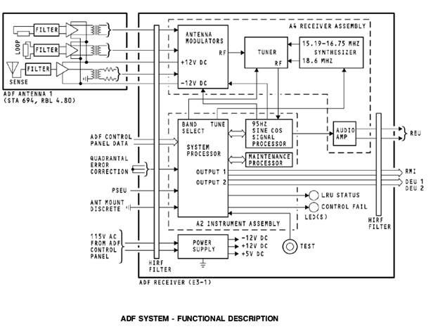
The ADF receiver contains two major assemblies, the A4 receiver assembly and the A2 instrument assembly.
The A4 receiver assembly contains the antenna modulators, tuner section, and synthesizer.
The modulator receives the input signals from the antenna assembly. The loop antenna inputs are modulated with a 95 Hz sine and cosine reference signal produced by the system processor. The modulated loop antenna signals are then summed with the sense antenna input. This composite signal then goes to a preselector filter in the tuner section.
The tuner section basically contains the receiver that processes the antenna inputs. The receiver tunes the frequency range of 190 to 1799 kHz. The tuner section receives the input signals from the antenna modulators and first sends it through a preselector filter. This preselector filter is made of six diode switched bandpass filters that are tuned to a specific portion of the ADF signal band. The filter is tuned by the system processor based on ADF control panel tune selections. From the preselector the signals are mixed with 15.19 through 16.75 MHz signal and an 18.6 MHz signal from the synthesizer. The signals are also filtered through a 15 MHz and 3.6 MHz to produce an intermediate frequency that can be processed by the ADF receiver.
The synthesizer uses binary tune data from the system processor to produce the injection frequencies to the mixers in the tuner section.
The A2 assembly contains the system processor, signal processor, and the maintenance processor. The system processor provides these functions:
· Format ADF bearing from the signal processor into an ARINC 429 bearing word
· Provide frequency tuning for the tuner section
· Perform functional test and power up tests
· Provide test results to the maintenance processor
· Transmit equipment identification and frequency data.
· Transmit station identification word and maintenance related words from the maintenance processor
· Store calibration constants in nonvolatile memory.
The signal processor provides these functions:
· Generate sine and cosine modulation to the ADF loop antenna modulators
· Receive analog data from tuner section
· Compute relative bearing to the station
· Detect 1020 Hz and 400 Hz identifier tones
· Provide audio output.
The maintenance processor provides these functions:
· Receives data from the maintenance bus inputs, stores time, date, and aircraft configuration and processes the maintenance control word.
· Store data from system processor in NVM.
· Determines validity of input maintenance word
· Formats fault summary word and sends it to the system processor
· Transfers all CMC interactive and normal mode data to system processor
· Provide maintenance menus in the airplane when requested
by the CMC
· Provide extended interactive mode support for troubleshooting data when LRU is removed from the airplane
· Monitor and decode the morse code station identification data from the Signal processor
· Format the station ident word
· Format the LRU ident message.
The signal processor receives the conditioned analog data from the tuner section and compares the signal to a 95 Hz reference signal to compute the station bearing and station identification and sends it to the system processor. The signal processor also sends audio and station identifier tones to the audio amp in the A4 receiver assembly that sends it to the REU.
The system processor receives all data bus and discrete inputs that come into the ADF receiver. The processor uses ADF control panel tune data to tune the antenna modulators and synthesizer. It sends the QEC program pin configuration to the signal processor to compensate for QEC. It also processes the air/ground and antenna mount discrete for memory. The signal processor receives the bearing computation and detected ident codes from the signal processor, formats the bearing data word, and sends the data out on two data buses. Output 1 goes to the RMI and output 2 goes to the DEUs.
Power
The ADF receiver power supply receives 115v ac, 400 Hz power from the ADF control panel. The power supply provides -12v dc, +12v dc, and +5v dc for internal use. The modulators send the 12v dc power outputs to the ADF antenna for operation.
Test
When you push the test switch on the ADF receiver front panel, the system processor starts a test of internal functions and checks the ADF control panel data word input. The antenna modulator removes power to the antenna assembly amplifiers. This causes no RF signal inputs to the antenna modulators. A test RF signal replaces the antenna RF input and the receiver sends the signal through its internal circuits. Test results show on the front panel LED status indicators.