Главная страница Случайная страница
КАТЕГОРИИ:
АвтомобилиАстрономияБиологияГеографияДом и садДругие языкиДругоеИнформатикаИсторияКультураЛитератураЛогикаМатематикаМедицинаМеталлургияМеханикаОбразованиеОхрана трудаПедагогикаПолитикаПравоПсихологияРелигияРиторикаСоциологияСпортСтроительствоТехнологияТуризмФизикаФилософияФинансыХимияЧерчениеЭкологияЭкономикаЭлектроника
Cooling System
|
|
CAUTION
Do not use compressed air during the valve check, or the vacuum valve may be damaged.
| Vacuum Valve Operation |
^ЩГ'Ш °

| Vacuum < •----------- ; . < 1.5cm Hg> ♦ |
| С |
| Air flows |
| ГШ |
© (mux
A
V[2]
| Air flows |
No Vacuum
Cooling System
Table of Contents
Exploded View....................................................................................................................................... 3-2
Coolant Flow Chart............................................................................................................................... 3-3
Specifications........................................................................................................................................ 3-4
Coolant.................................................................................................................................................. 3-5
Coolant Level Inspection................................................................................................................. 3-5
Coolant Draining.............................................................................................................................. 3-5
Coolant Filling................................................................................................................................. 3-6
Pressure Testing............................................................................................................................. 3-7
Water Pump........................................................................................................................................... 3-8
Water Pump Removal...................................................................................................................... 3-8
Water Pump Installation.................................................................................................................. 3-8
Water Pump Inspection................................................................................................................... 3-8
Radiator, Radiator Fan.......................................................................................................................... 3-9
Radiator, Radiator Fan Removal.................................................................................................... 3-9
Radiator Inspection....................................................................................................................... 3-10
Radiator Cap Inspection................................................................................................................ 3-10
Thermostat.......................................................................................................................................... 3-12
Removal......................................................................................................................................... 3-12
Installation..................................................................................................................................... 3-12
Inspection...................................................................................................................................... 3-12
Radiator Fan Switch, Water Temperature Sensor............................................................................. 3-13
Radiator Fan Switch, Water Temperature Sensor Removal........................................................ 3-13
Radiator Fan Switch, Water Temperature Sensor Installation..................................................... 3-13
Radiator Fan Switch, Water Temperature Sensor Inspection...................................................... 3-13
Exploded View

|
1. Radiator Fan Switch 5. Water Filter
2. Water Temperature Sensor 6. Valve Assy
3. Air Bleeder Bolt
4. Drain Plug
EO: Apply engine oil.
SS: Apply silicone sealant.
T1: 2.5 N-m (0.25 kg-m, 22 in-lb)
T2: 9.8 N-m (1.0 kg-m, 87 in-lb)
T3: 18 N-m (1.8 kg-m, 13.0 ft-lb)
T4: 7.8 N-m (0.80 kg-m, 69 in-lb)
Coolant Flow Chart

|
1. Water Pump coupled with oil pump
2. Air Bleeder Bolt
3. Cylinder Jacket
4. Cylinder Head Jacket
5. Thermostat
6. Water Temperature Sensor
7. Hole (Air bleeder hole)
When the engine is cold, the thermostant is closed so that the coolant flow is restricted through the air bleeder hole, causing the engine to warm up more quickly.
9. To Reserve Tank
When the engine is very hot, the pressure valve in the radiator cap allows air and vapor to escape into the reserve tank. When the engine cools down, the pressure drop draws the vacuum valve (another small valve) open, admitting coolant from the reserve tank into the radiator.
10. Reserve Tank
11. Radiator
12. Radiator Fan
13. Radiator Fan Switch
14. Liquid-cooled Oil Cooler
| 15. Drain Bolt |
8. Radiator Cap
3-4 COOLING SYSTEM Specifications
| Item | Standard |
| Coolant provided when shipping: Type Color Mixed ratio Freezing point Total amount | Permanent type antifreeze (soft water and ethylene glycol plus corrosion and rust inhibitor chemicals for aluminum engines and radiators) Green Soft water 50%, coolant 50% -35°C (-3VF) 2.4L (reserve tank full level including radiator and engine) |
| Radiator cap Relief pressure: | 93 - 123 к Pa (0.95 - 1.25 kg/cm', 14 - 18 psi) |
| Thermostat: Valve opening temperature Valve full opening lift | 80 - 84-C (176 - 183 -F) 8mm or more @95°C (203 °F) |
Sealant - Kawaaakl Bond (Silicone Sealant): 56019-120

|

|
Coolant
Coolant Level Inspection
NOTE
О Check the level when the engine is cold (room or ambient temperature).
•Check the coolant level in the reserve tank with the motorcycle held perpendicular.
*lf the coolant level is lower than the " L" (Low) level line [A], add coolant to the " F" (Full) level line [В].
________________________ CAUTION ____
For refilling, add the specified mixture of coolant and soft water. Adding water alone dilutes the coolant and degrades its anticorro- slon properties. The diluted coolant can attack the aluminum engine parts. In an emergency, soft water alone can be added. But the diluted coolant must be returned lo the correct mixture ratio within a few days.

|
If coolant must be added often, or the reservoir lank has run completely dry; there Is probably leakage In the cooling system. Check the system for leaks.
Coolant Draining
AWARNING
To avoid bums, do not remove the radiator cap or try lo change the coolant when the engine is still hoi. Wait until it cools down. Coolant on tires will make them slippery and can cause an accident and injury. Immediately wipe up or wash away any coolant that spills on the frame, engine, or other painted parts. Since coolant is harmful lo the human body, do not use for drinking.
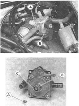
• Remove:
Hose [A]
Mounting Bolts [B] and Reserve Tank [C]

|
• Remove the cap [D] and pour the coolant into a container.
Coolant Filling •Tighten the drain plug.
Torque - Drain Plug: 9.8 N-m (1.0 kg-m, 87 in-lb)
• Fill the radiator up to the thermostat housing cover [A] filler neck [B] with coolant and install the radiator cap.
NOTE
О Pour in the coolant slowly so that it can expel the air from the engine and radiator.
• Fill the reserve tank up to the " F" level line with coolant, and install the cap.