Главная страница Случайная страница
КАТЕГОРИИ:
АвтомобилиАстрономияБиологияГеографияДом и садДругие языкиДругоеИнформатикаИсторияКультураЛитератураЛогикаМатематикаМедицинаМеталлургияМеханикаОбразованиеОхрана трудаПедагогикаПолитикаПравоПсихологияРелигияРиторикаСоциологияСпортСтроительствоТехнологияТуризмФизикаФилософияФинансыХимияЧерчениеЭкологияЭкономикаЭлектроника
Engine Lubrication System
|
|
Table of Contents
Engine Oil Flow Chart............................................................................................................................ 6-2
Exploded View........................................................................................................................................ 6-4
Specifications......................................................................................................................................... 6-5
Engine Oil and Oil Filter........................................................................................................................ 6-6
Oil Level Inspection.......................................................................................................................... 6-6
Engine Oil Change............................................................................................................................ 6-6
Oil Filter Change............................................................................................................................... 6-7
Oil Cooler............................................................................................................................................... 6-8
Oil Cooler Removal.......................................................................................................................... 6-8
Oil Cooler Installation....................................................................................................................... 6-8
Oil Pan.................................................................................................................................................... 6-9
Oil Pan Removal............................................................................................................................... 6-9
Oil Pan Installation............................................................................................................................ 6-9
Oil Pump............................................................................................................................................... 6-10
Oil Pump Removal.......................................................................................................................... 6-10
Oil Pump Installation....................................................................................................................... 6-10
Oil Pressure Measurement.................................................................................................................. 6-11
Relief Valve Opening Pressure Measurement............................................................................... 6-11
Oil Pressure Measurement............................................................................................................. 6-11
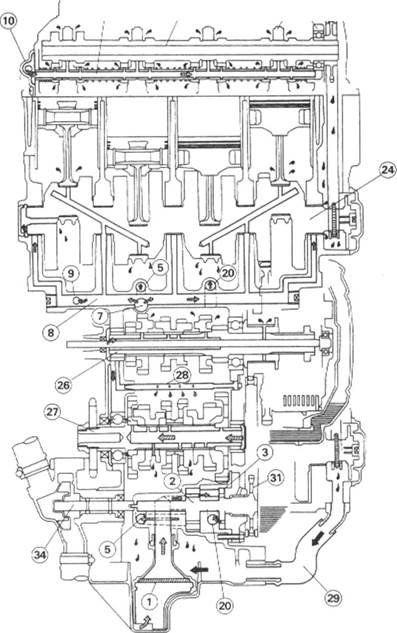
Engine Oil Flow Chart
1. Oil Screen
2. Oil Pump Main Rotor
3. Oil Pump Subrotor
4. Relief Valve for Main Oil
Passage
5. Oil Passage to Oil Filter
6. Oil Filter
7. Oil Passage from Oil Filter
8. Main Oil Passage
9. Oil Hose to Cylinder Head
10. Left Side Cylinder Head
Cover
11. Camshaft Caps
12. Camshafts
13. Rocker Shafts
14. Oil Nozzle
15. Alternator Shaft Oil Pipe
16. Alternator Shaft
17. Alternator
18. Electric Starter
19. Relief Valve for Oil Cooler
20. Oil Passage to Oil Cooler
21. Liquid Cooled Oil Cooler
22. Water Hoses
(see Coolant Flow Chart)
23. Oil Pan
24. Crankshaft
25. Oil Pipe for Transmission
Shafts
26. Drive Shaft
27. Output Shaft
28. Oil Pipe for Gears
29. Oil Return Hose
30. Oil Pressure Switch
31. Oil Pump Sprocket
32. Breather Hose
33. Air Cleaner Housing
34. Water Pump
| i^v? / - |
| : Hot Oil < J=3: Cold Oil *--------: Blowby Gas Oil Flow: |
| L |
35. Oil Drain Plug
Apply engine oil.

| T1: T2: T3: T4: T5: T6: T7: T8: T9: |
Apply a non-permanent locking agent. Replacement Parts Apply silicone sealant.
20 N-m (2.0 kg-m, 14.5 ft-lb) Hand-tight or 9.8 N-m (1.0 kg-m,
| EO: L R: SS: |
87 in-lb) 25 N-m (2.5 kg-m, 18.0 ft-lb) 12 N-m (1.2 kg-m, 104 in-lb) 15 N-m (1.5 kg-m, 11.0 ft-lb) 49 N-m (5.0 kg-m, 36 ft-lb) 2.5 N-m (0.25 kg-m, 22 in-lb) 9.8 N-m (1.0 kg-m, 87 in-lb) 34 N-m (3.5 kg-m, 25 ft-lb)
Exploded View
EO: Apply engine oil.
L Apply a non-permanent locking agent. R: Replacement Parts SS: Apply silicone sealant
T1: 20 N-m (2.0 kg-m, 14.5 ft-lb) T2: Hand-tight or 9.8 N-m (1.0 kg-m,

87 in-lb) T3: 25 N-m (2.5 kg-m, 18.0 ft-lb) T4: 12 N-m (1.2 kg-m, 104 in-lb) T5: 15 N-m (1.5 kg-m, 11.0 ft-lb) T6: 49 N-m (5.0 kg-m, 36 ft-lb) T7: 2.5 N-m (0.25 kg-m, 22 in-lb) T8: 9.8 N-m (1.0 kg-m, 87 in-lb) T9: 34 N-m (3.5 kg-m, 25 ft-lb)
Specifications
| Item | Standard |
| Engine Oil: Grade Viscosity Capacity Level | SE. SF, or SG class SAE 10W-40, 10W-50, 20W-40, or 20W-50 3.4L (when filter is not removed) 3.5L (when filter is removed) 4.0L (when engine is completely dry) Between upper and lower level lines |
| Oil Pressure Measurement: Relief valve opening pressure Oil pressure @4, 000 r/min(rpm), oil temp. 90'C(194eF) | 430 - 590 kPa (4.4 - 6.0 kg/cm3, 63 ~ 85 psi) 305 ~ 365 kPa(3.1 - 3.7 kg/cm2, 44 - 53 psi) |
| Special Tools - Oil Filter Wrench: 57001-1249 Oil Pressure Gauge, 10 kg/cm^: 57001-164 Oil Pressure Gauge Adapter, PT 57001-1033 Bearing Driver Set 57001-1129 |
Sealant - Kawasaki Bond (Silicone Sealant): 56019-120
|

|
Engine Oil and Oil Filter
A WARNING
Motorcycle operation with insufficient, deteriorated, or contaminated engine oil will cause accelerated wear and may result in engine or transmission seizure, accident, and injury.
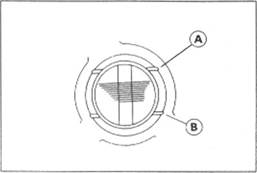
Oil Level Inspection
• Check that the engine oil level is between the upper [A] and lower [B] levels in the gauge.
NOTE
О Situate the motorcycle so that it is perpendicular to the ground.
О If the motorcycle has just been used, wart several minutes for all the oil to drain down.
О If the oil has just been changed, start the engine and run it for several minutes at idle speed. This fills the oil filter with oil. Stop the engine, then wait several minutes until the oil settles.
|
Oil Cooler
OH Cooler Removal
• Drain:
Engine Oil (see Engine Oil Change) Coolant (see Cooling System chapter)
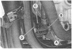
• Remove the oil cooler hose [A] from the radiator.
• Remove:
Oil Cooler Bolt [AJ Oil Cooler [B]
• Remove the oil cooler hoses [A] from the oil cooler.
Oil Cooler Installation
• Installation is the reverse of removal. Note the following.
• Install the oil cooler so that the crankcase rib [A] fits the slot [ B] of the oil cooler.
• Apply engine oil to the oil cooler bolt and tighten it. Torque - Oil Cooler Bolt 49 N-m (5.0 kg-m, 36 ft-lb)
*lf the muffler is not removed, the oil cooler bolt can be tightened to the specified torque using a wrench and a hand spring scale. Pull the wrench at a point of 300 mm from the center of the bolt with the spring scale unit it indicates 17 kg.
• Pour:

Engine Oil (see Engine Oil Change) Coolant (see Cooling System chapter)
Oil Pan
Oil Pan Removal
• Drain:
Engine Oil (see Engine Oil Change) Coolant (see Cooling System chapter)
• Remove:

|

|
Radiator (see Cooling System chapter) Muffler (see Engine Top End chapter) Down Tubes [A]
Oil Hose [A] Oil Pan Bolts [B] Oil Pan [C]
О Remove the oil pipe [A], oil pressure relief valves [B] and oil screen [C] as necessary.
Oil Pan Installation
• Replace the oil pan gasket with a new one.

|
• Replace the O-ring [A] with a new one if it is damaged. The O-ring between the oil pan and the crankcase must be installed with the flat side [B] facing the crankcase.
•Apply a non-permanent locking agent to the threads of the relief valves [A], and tighten them.
Torque - Oil Pressure Relief Valves: 15 N-m (1.5 kg-m, 11.0 ft-lb)
• Install the oil screen so that the crankcase rib [B] fits the slot [Cj of
the oil screen. •Tighten the oil pan bolts.

Torque - Oil Pan Bolts: 12 N-m (1.2 kg-m, 104 In-lb)
Oil Pump
Oil Pump Removal
• Drain the engine oil (see Engine Oil Change)
• Remove:
Right Lower Fairing (see Frame chapter)
Clutch (see Clutch chapter)
Alternator Chain (see Crankshaft/Transmission)
Oil Pump Bolts [A]

|
Oil Pump Assembly [B]
Oil Pump Installation
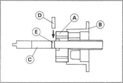
О When pressing the needle bearing [A] into the pump cover [B], align the Ф2.5 mm hole [C] in the bearing with the Ф3.0 mm hole [D] in the cover.
|
Special Tool - Bearing Driver Set 57001-1129
• Install the main rotor [A] and the pump body [B] onto the pump shaft [С].

• Install the pin [D] into the pin hole [Е].

|
• Install the subrotor [A] so that the mark [B] on the subrotor aligns with the pin [С].
__________________________________________________ ENGINE LUBRICATION SYSTEM 6-11
|
Oil Pressure Measurement
Relief Valve Opening Pressure Measurement
NOTE
О Measure the oil pressure before the engine is warmed up if you want to test relief valve opening pressure.
• Remove:
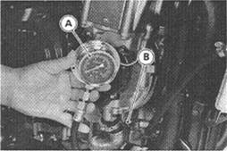
Right Lower Fairing (see Frame chapter) Oil Pressure Switch •Attach the oil pressure gauge [A] and adapter [B] to the oil pressure switch hole.
Special Tools - Oil Pressure Gauge, 10 kg/cm2: 57001-164
Oil Pressure Gauge Adapter, PT K: 57001-1033
AWARNING
To prevent a fire, be sure 1o keep the oil pressure gauge hose away from the exhaust pipe.
• Read the maximum oil pressure while running the engine at various speeds. A normal relief valve keeps the maximum oil pressure between the specified values.
Relief Valve Opening Pressure
Standard: 430 - 590 kPa (4.4 - 6.0 kg/cnr, 63 - 85 psi)
*lf the reading is much higher than the standard or is much lower than the standard, check the left relief valve, the oil pump, or the oil passages.
•Apply silicone sealant to the oil pressure switch, and tighten rt. Sealant - Kawasaki Bond (Silicone Sealant): 56019-120 Torque - Oil Pressure Switch: 15 N-m (1.5 kg-m, 11.0 ft-lb)
OH Pressure Measurement
NOTE
О Measure the oil pressure after the engine is warmed up.
•Attach the oil pressure gauge and adapter to the oil pressure switch hole (see Relief Valve Opening Pressure Measurement).
AWARNING
To prevent a fire, be sure to keep the oil pressure gauge hose away from the exhaust pipe.