Главная страница Случайная страница
КАТЕГОРИИ:
АвтомобилиАстрономияБиологияГеографияДом и садДругие языкиДругоеИнформатикаИсторияКультураЛитератураЛогикаМатематикаМедицинаМеталлургияМеханикаОбразованиеОхрана трудаПедагогикаПолитикаПравоПсихологияРелигияРиторикаСоциологияСпортСтроительствоТехнологияТуризмФизикаФилософияФинансыХимияЧерчениеЭкологияЭкономикаЭлектроника
CAUTION___
|
|
The upper and lower crankcase halves are machined at the factory In the assembled state, so the crankcase halves must be replaced as a set.
•With a high-flash point solvent, clean off the mating surfaces of the crankcases halves and wipe dry.
• Using compressed air, blow out the oil passages in the crankcase halves.
• Install:
Camshaft Chain [A]
Crankshaft and Connecting Rods [B]
Alternator Shaft and Starter Clutch Assembly [C]
Starter Motor Idle Gear Assembly [D]
Transmission Oil Pipe [E]
Dowel Pins [F]
Nozzle and O-ring [G]
Plug [H]
Set Pins [I]
Set Rings [J]
Transmission Shafts and Gears Shift Drum

|
Shift Forks and Shift Rods

|
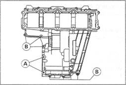
• Before fitting the lower case on the upper case, check the following. О Be sure to hang the camshaft chain [A] on the crankshaft. О Check the nozzle [B] so that the bigger diameter side faces upward. О Check to see that the shift drum and transmission gears are in the neutral position.
•Apply silicone sealant [A] to the mating surface of the lower crankcase half.

|
Sealant - Kawasaki Bond (Silicone Sealant): 56019-120
CAUTION

|

|

|
Crankshaft and Connecting Rods
Crankshaft Removal
•Spirt the crankcase (see Crankcase Splitting). • Remove the crankshaft.
Crankshaft Installation
OThe connecting rod big end is bolted using the " plastic region fastening method".
OThis method precisely achieves the needed clamping force without exceeding it unnecessarily, allowing the use of thinner, lighter bolts further decreasing connecting rod weight.
OThere are two types of the plastic region fastening. One is a bolt length measurement method and other is a tightening torque method. Observe one of the following two, but the bolt length measurement method is preferable because this is a more reliable way to tighten the big end nuts.
___________________ CAUTION
The connecting rod bolts are designed to stretch when tightened. Never reuse the connecting rod bolts. See the table below for correct bolt and nut usage.
(1) Bolt Length Measurement Method
• Be sure to clean the bolts, nuts, and connecting rods thoroughly with high-flash point solvent, because the new connecting rods, bolts, and nuts are treated with an anti-rust solution.
Л WARNING

|
Clean the bolts, nuts, and connecting rods in a well-ventilated area, and take care that there is no spark or flame anywhere near the working area. This includes any appliance with a pilot light Because of the danger of highly flammable liquids, do not use gasoline or iow-flash point solvents to clean them.
| Connecting Rod Assy | Bolt | Nut | Usable Range of Connecting Rod Bolt Stretch |
| New | Use the bolts attached to new con-rod. | Attached to new con-rod | 0.20 - 0.32 mm |
| New | |||
| Used- | Replace the bolts with new ones. | Used | 0.24 - 0.36 mm |
| New |
(2) Tightening Torque Method
*lf you don't have a point micrometer, you may tighten the nuts using the " Tightening Torque Method".
• Be sure to clean the bolts, nuts, and connecting rods thoroughly with high-flash point solvent, because the new connecting rods, bolts, and nuts are treated with an anti-rust solution.
ik WARNING
Clean the bolts, nuts, and connecting rods in a well-ventilated area, and lake care that there is no spark or flame anywhere near the working area. This Includes any appliance with a pilot light. Because Ы the danger of highly flammable liquids, do not use gasoline or low-flash point solvents to clean them.
_ ____________________ CAUTION
Immediately dry the bolts and nuts with compressed air after cleaning.
Clean and dry the bolts and nuts completely.

|
| Connecting Rod Assy | ————— Bolt | Nut | Torque + Angle N-m (kg-m, ft-lb) |
| New | Use the bolts attached to new con-rod. | Attached to new con-rod | 18 (1.8, 13.0) + 120° |
| New | 20 (2.0, 14.5) + 120[4] | ||
| Used | Replace the bolts with new ones | Used | 24 (2.4.17.4) + 120* |
| New | 25 (2.6.18.8) + 120' |
| CAUTION |

|
• Measure the connecting rod big end bore diameter, and mark each connecting rod big end in accordance with the bore diameter.
Bore Diameter Mark (Around Weight Mark) [A]: " O" or no mark.
NOTE
О Tighten the connecting rod big end nuts to the specified torque (see
Connecting Rod Installation). О The mark already on the big end should almost coincide with the measurement.
Connecting Rod Big End Bore Diameter Marks None 38.000 ~ 38.008 mm
О 38.009 - 38.016 mm
•Select the proper bearing insert in accordance with the combination

|

|
of the connecting rod and crankshaft coding. • Install the new inserts in the connecting rod and check insert/crankpin clearance with the plastigage.
| Con-rod Big End Bore Diameter' Marking | Crankpin Diameter Mark | Bearing Insert | |
| Size Color | Part Number | ||
| None | О | Brown | 92028-1714 |
| None | None | Colorless | 92028-1713 |
| О | О | ||
| О | None | Blue | 92028-1712 |
Crankshaft Main Bearing Insert/Journal Wear • Using a plastigage (press gauge) [A], measure the bearing insert/journal [B] clearance.
NOTE
О Tighten the crankcase bolts to the specified torque (see Crankcase Assembly).
О Do not turn the crankshaft during clearance measurement. О Journal clearance less than 0.025 mm can not be measured by plastigage, however, using genuine parts maintains the minimum standard clearance.
Crankshaft Main Bearing insert/Journal Clearance Standard: 0.020 ~ 0.044 mm Service Limit 0.07 mm

|
*lf clearance is within the standard, no bearing replacement is required. *lf clearance is between 0.044 mm and the service limit (0.07 mm), replace the bearing inserts with inserts painted blue [CJ. Check insert/journal clearance with the plastigage. The clearance may exceed the standard slightly, but it must not be less than the minimum in order to avoid bearing seizure. *lf clearance exceeds the service limit, measure the diameter of the crankshaft main journal.
Crankshaft Main Journal Diameter Standard: 32.984 ~ 33.000 mm Service Limit 32.96 mm
*lf any journal has worn past the sen/ice limit, replace the crankshaft with a new one.
*lf the measured journal diameters are not less than the service limit but do not coincide with the original diameter markings on the crankshaft, make new marks on it
Crankshaft Main Journal Diameter Marks None 32.984 - 32.992 mm
1 32.993 - 33.000 mm
cm

|
□: Crankshaft Main Journal Diameter Marks, " 1" mark or no mark
• Measure the main bearing bore diameter, and mark the upper crankcase half in accordance with the bore diameter. O: Crankcase Main Bearing Bore Diameter Marks, " O" mark or no mark.
NOTE
О Tighten the crankcase boits to the specified torque (see Crankcase Assembly).

|
OThe mark already on the upper crankcase half should almost coincide with the measurement.
Crankcase Main Bearing Bore Diameter Marks О 36.000 - 36.008 mm
None 36.009 - 36.016 mm
•Select the proper bearing insert in accordance with the combination
of the crankcase and crankshaft coding. • Install the new inserts in the crankcase halves and check insert/journal clearance with the plastigage.
| Crankcase Main Bearing Bore Diameter Marking | Crankshaft Main Journal Diameter Marking | Bearing Insert' | ||
| Size Color | Part Number | Journal Nos. | ||
| О | Brown | 92028-1717 | 1, 3, 5 | |
| 92028-1720 | 2, 4 | |||
| None | Colorless | 92028-1716 | 1, 3, 5 | |
| О | None | 92028-1719 | 2, 4 | |
| None | None | Blue | 92028 1715 | 1, 3, 5 |
| 92028-1718 | 2, 4 |
| *The bearing inserts for Nos. 2 and 4 journals have an oil groove, respectively. |
Crankshaft Side Clearance
•Insert a thickness gauge between the crankcase main bearing and the
crank web at the No. 2 journal [A] to determine clearance [В]. *lf the clearance exceeds the service limit replace the crankcase halves [C] as a set.
_________________________ CAUTION__________________________
The upper and lower crankcase halves are machined at the factory in the* assembled state, so the crankcase halves must be replaced as a set.
Crankshaft Side Clearance

|
Standard: 0.05 ~ 0.20 mm Service Limit 0.40 mm
Alternator Chain / Alternator Shaft / Starter Clutch
Alternator Chain Adjustment
NOTE
О If the alternator chain [/1] makes noise, adjust the upper alternator chain tensioner [А].
• Remove:
Clutch (see Clutch chapter) Lower Alternator Chain Tensioner [C]
• Loosen:
Upper Alternator Chain Tensioner Pivot Bolt [A] Upper Alternator Chain Tensioner Set Bolt [B] Upper Alternator Chain Tensioner Locknut [C] •Turn the upper alternator chain tensioner adjusting bolt [D] counterclockwise until the lower part of the chain is taut, and touch the head of adjusting bolt to crankcase [Е]. •Apply a non-permanent locking agent to the threads of chain tensioner pivot bolt and set bolt, and tighten them.

|
Torque - Upper Alternator Chain Tensioner Pivot Bolt 12 N-m (1.2 kg-m, 104 In-lb) Upper Alternator Chain Tensioner Set Bolt: 12 N-m (1.2 kg-m, 104 In-lb)
• Push the lower alternator chain tensioner pawl [A] to release the tensioner rod and push the rod [В].
•While holding the tensioner rod, install the lower alternator chain tensioner.

|
•Apply a non-permanent locking agent to the threads of chain tensioner bolts, and tighten them.
Torque - Lower Alternator Chain Tensioner Bolts: 12 N-m (1.2 kg-m, 104 In-lb)
Alternator Chain Removal • Remove:
Clutch (see Clutch chapter) Lower Alternator Chain Tensioner [A] Upper Alternator Chain Tensioner [B] Alternator Shaft Oil Pipe [C] Circlips [D]

Special Tool - Outside Circlip Pliers: 57001-144
• Remove the alternator chain along with the drive sprocket [A], collar [B], alternator driven sprocket [C], oil pump driven sprocket [D], and the chain guide [Е].
Alternator Chain Installation • Install:
Chain Guide
Drive Sprocket and Collar
Oil Pump Driven Sprocket
Alternator Chain and Alternator Driven Sprocket
Circlips -
Alternator Shaft Oil Pipe •Apply a non-permanent locking agent to the threads of the alternator shaft oil pipe bolt and tighten it.
Torque - Alternator Shaft Oil Pipe Bolt 12 N-m (1.2 kg-m, 104 In-lb)
•Adjust the alternator chain (see Alternator Chain Adjustment).
Alternator Shaft, Starter Clutch Removal
• Remove:
Engine (see Engine Removal/Installation)
Alternator
Pickup Coil Cover
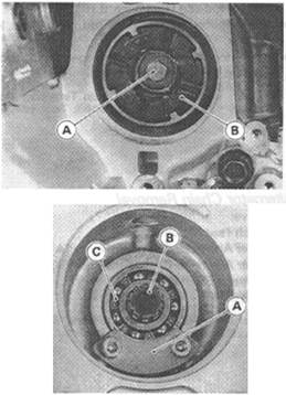
• Unscrew the alternator shaft bolt [A] while holding the timing rotor hexagon head, and remove the alternator coupling dampers [В].
•Split the crankcase (see Crankcase Splitting). • Remove:,

|
Drive Shaft and Output Shaft Alternator Shaft Bearing Holder [A] Alternator Shaft [B] and Alternator Shaft Bearing [C] Starter Clutch
Alternator Shaft Starter Clutch Installation
*lf the alternator shaft right end ball bearing is removed, replace the
bearing with a new one. О Press the bearing with the bearing driver set until it stops.
Special Tool - Bearing Driver Set: 57001-1129
•Apply a non-permanent locking agent to the threads of the alternator shaft bearing holder bolts, and tighten them.
Torque - Alternator Shaft Bearing Holder Bolts: 12 N-m (1.2 kg-m, 104 in-lb)

|
• Hold the timing rotor hexagon head, tighten the coupling bolt. Torque - Alternator Shaft Bolt 25 N-m (2.5 kg-m, 18.0 ft-lb)
Starter Clutch Disassembly
• Remove the circlip [A] and flat washer [В].
• Pull the starter clutch gear and take off the needle bearing and flat washer.
• Holding the starter clutch assembly in a vise, remove the holder Allen bolts and take off the one-way clutch.

|
Special Tools - Outside Circlip Pliers: 57001-144 Inside Circlip Pliers: 57001-143
Starter Clutch Assembly
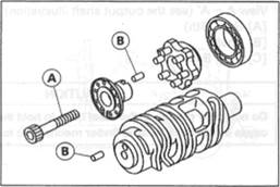
• Be sure to install the one-way clutch [A] so that the flange [B] of it
fits in the holder recess [С]. •Apply a non-permanent locking agent to the threads of the starter clutch holder botls, and tighten them.
Torque - Starter Clutch Holder Bolts: 12 N-m (1.2 kg-m, 104 In-lb)
|
Special Tools - Inside Circlip Pliers: 57001-143 Outside Circlip Pliers: 57001-144
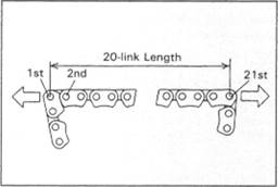
Alternator Shaft Chain Wear
• Hold the alternator shaft chain so that it may be pulled tight.
• Measure the length of 20 links (21 pins) with a vernier caliper.
*lf the 20 link length of the alternator shaft chain is greater than the service limt replace it.
Alternator Shaft Chain 20 link Lengh Standard: 158.8 - 1592 mm Service Limit 159.8 mm
Chain Guide Wear
•Visually inspect the rubber on the guide.

|
*lf the rubber is cut or damaged in any way, replace the guide.
Starter Clutch Inspection
• Remove the starter motor.
•Turn the starter motor idle gear [A] by hand. When viewed from the left side of the engine, the idle gear should turn counterclockwise freely [B], but should not turn clockwise [С]. *lf the starter clutch does not operate as it should or if it makes noise, go to the next step.
• Disassemble the starter clutch, and visually inspect the clutch parts. *lf there is any worn or damaged part, replace it.
NOTE
О Examine the starter dutch gear as well. Replace it if it is worn or damaged.
Starter Motor Idle Gear
Starter Motor Idle Gear Removal
• Remove:
Alternator Shaft [A] and Starter Clutch [B] (see Alternator Shaft, Starter Clutch Removal).
• Pull out the starter motor idle gear shaft and take off the idle gear [С].
Starter Motor Idle Gear Installation

|
• Install the starter motor idle gear so that the small diameter gear [D] faces the starter motor side (right side).
Transmission
Shift Pedal Removal
•Mark the position of the shift lever on the shift shaft so that it can be

|
installed later in the same position. • Remove the shift lever and shift pedal.
Shift Pedal Installation
• Install the shift pedal [A] so that the shift lever [B] positions at right angles [C] with the shift rod [D] and the center of the shift pedal meets the center line [E] of the shift rod by loosening the front and rear locknuts [F] and turning the rod.
NOTE
О The locknut next to the knurled portion of the rod has left-hand threads.
*lf necessary, adjust the pedal position from the standard position to suit you as follows.

|
• Loosen the front and rear rod locknuts. •Turn the rod to adjust the pedal position. •Tighten the locknuts securely.
External Shift Mechanism Removal
• Remove:
Left Lower Fairing (see Frame chapter) Water Pump (see Cooling System chapter) Engine Sprocket (see Final Drive chapter) Shift Pedal (see Shift Pedal Removal) Rear Wheel (see Wheels/Tires chapter)
• Move the rear part of the drive chain toward the right [A] and then move the front part toward the rear to clear the output shaft [В].
• Remove the swingarm pivot shaft [C] and upper shock absorber bolt [D] (see Suspension chapter).
• Move the drive chain toward the left and put the chain on the chain guard.

• Remove the shift shaft [A] while pushing [B] the shift mechanism arm [C] toward the shaft.
• Remove: Bolt [A]
Gear Positioning Lever [B] Spring [C] Nut [D]

|
Neutral Positioning Lever [E] Spring [F]
Externai Shift Mechanism Installation
•Install the gear positioning lever [A] and neutral positioning lever [B] as shown. Springs [C] Collars [E]
Washer [D] Nut [F]
Torque - Neutral Positioning Lever Nut 9.8 N-m (1.0 kg-m, 87 in-lb)
•Apply a non-permanent locking agent to the threads of the gear positioning lever bolt [G], and tighten it.

Torque - Gear Positioning Lever Bolt 9.8 N-m (1.0 kg-m, 87 in-lb)
•Apply silicone sealant to the crankcase halves mating surface on the front and rear sides of the external shift mechanism cover mount.
Sealant - Kawasaki Bond (Silicone Sealant): 58019-120 [A]
External Shift Mechanism Assembly
•Install the return spring [A] on the shift mechanism arm [B], noting the hook direction.
Transmission Shaft Removal
•Split the crankcase (see Crankcase Splitting).
• Remove the drive shaft [A] and output shaft [BJ.
Transmission Shaft Installation
•Apply engine oil to the sliding portion of the gears and bearings. •Check to see that the set pins [A] and set rings [B] are in place. • Install the drive shaft and output shaft into the upper crankcase half.
Transmission Disassembly
• Remove the transmission shafts (see Transmission Shaft Removal).
• Remove the circlips, disassemble the transmission shafts.
Special Tool - Outside Clrcllp Pliers: 57001-144
•The 5gh gear [A] on the output shaft has three steel balls assembled into it for the positive neutral finder mechanism. Remove the 5th gear. О Set the output shaft in a vertical position holding the 3rd gear [В]. О Spin the 5th gear quickly [C] and pull it off upward.
Transmission Assembly

|
• Install the. gear bushings [A] on the shaft with their oil holes [B] aligned with the shaft oil holes.
• Fit the steel balls into the 5th gear holes as shown. View A - A' (see the output shaft illustration)
[A] Gear (5th)
[B] Shaft
[C] Steel Balls
______________________ CAUTION_____________________

|
Do no< apply grease! o the steel balls to hold them In place. This will cause the positive neutral finder mechanism to malfunction.
• Replace any circlip that were removed with new ones.

|
• Instal the circlips [A] so that the opening is aligned with a spline groove [В].
Shift Drum and Fork Removal
• Remove:
Lower Crankcase Half (see Crankcase Splitting)
External Shift Mechanism (see External Shift Mechanism Removal)
Shift Rod Retainer [A] (Right)
Shift Drum Bearing Holder [B] (Left)
• Pull out the shift rods [C], and take off the shift forks.

|
• Pull out the shift drum [D].
Shift Drum and Fork Installation
• Install the shift rods, noting the groove position. The rods are identical. •Three shift forks are used. Fit each shift fork into the groove of the
proper gear so that the shift fork guide pin is in the proper groove on the shift drum.
• Position the one with shortest ears on the drive shaft and place the pin in the center groove in the shift drum.
• Of the two forks on the output shaft each longer rib faces inward.
[A] Shift Rods [D] Longer Forks (output)
[B] Grooves [E] Longer Ribs
[C] Shorter Fork (drive) [F] Front
•Apply a non-permanent locking agent to the threads of the shift rod retainer bolt and shift drum bearing holder bolts, and tighten them.
Torque - Shift Rod Retainer Bolt: 12 N-m (1.2 kg-m, 104 in-lb)

|
Shift Drum Bearing Holder Bolts: 12 N-m (1.2 kg-m, 104 in-lb)
Shf/t Drum Disassembly
• Remove the shift drum (see Shift Drum and Fork Removal), •while holding the shift drum with a vise, remove the shift drum cam holder bolt
[A] Shift Drum Cam Holder Bolt
[B] Dowel Pins
Shfrt Drum Assembly • Be sure to install the dowel pins.
•Apply a non-permanent locking agent to the threads of the shift drum cam holder bolt, and thighten it.
|
Torque - Shfrt Drum Cam Holder Bolt 12 N-m (1.2 kg-m, 104 In-lb)
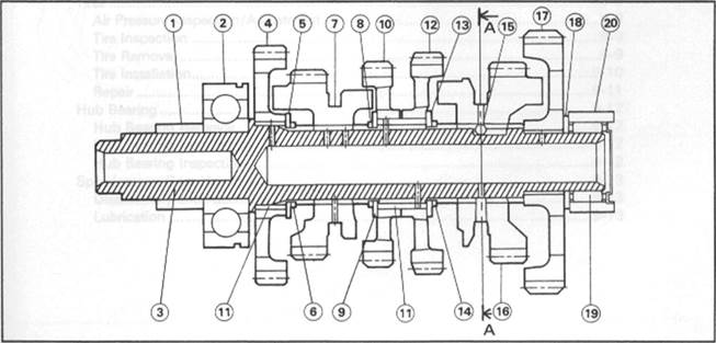
Drive Shaft

|
1. Bearing Outer Race 7. Bushing 13. 5th Gear
2. Circlip 8. Toothed Washer 14. Bushing
3. Needle Bearing 9. Circlip 15.1st Gear (Drive Shaft)
4. Thrust Washer 10. 3rd/4th Gear 16. Ball Bearing
5. 2nd Gear 11. Circlip
6. Top (6th) Gear 12. Toothed Washer
Output Shaft
|
8. Circlip
9. Toothed Washer
10. 4th Gear
11. Bushing
12. 3rd Gear
13. Toothed Washer
| 1. Collar (force fit) 2. Ball Bearing 3. Output Shaft 4. 2nd Gear 5. Toothed Washer 6. Circlip 7. Top (6th) Gear |
14. Circlip
15. Steel Ball
16. 5th Gear 17.1st Gear
18. Thrust Washer
19. Needle Bearing
20. Bearing Outer Race