Главная страница Случайная страница
КАТЕГОРИИ:
АвтомобилиАстрономияБиологияГеографияДом и садДругие языкиДругоеИнформатикаИсторияКультураЛитератураЛогикаМатематикаМедицинаМеталлургияМеханикаОбразованиеОхрана трудаПедагогикаПолитикаПравоПсихологияРелигияРиторикаСоциологияСпортСтроительствоТехнологияТуризмФизикаФилософияФинансыХимияЧерчениеЭкологияЭкономикаЭлектроника
Crankshaft I Transmission
|
|
Table of Contents
Exploded View................................................................. 8-2
Specifications.................................................................. 8-4
Crankcase Splitting......................................................... 8-6
Crankcase Splitting..................................................... 8-6
Crankcase Assembly.................................................. 8-6
Crankshaft and Connecting Rods................................... 8-8
Crankshaft Removal.................................................... 8-8
Crankshaft Installation................................................ 8-8
Connecting Rod Removal........................................... 8-8
Connecting Rod Installation........................................ 8-8
Connecting Rod Big End Bearing
Insert/Crankpin Wear................................................ 8-11
Crankshaft Main Bearing Insert/Journal Wear., 8-12
Crankshaft Side Clearance....................................... 8-14
Alternator Chain / Alternator Shaft /
Starter Clutch............................................................. 8-15
Alternator Chain Adjustment..................................... 8-15
Alternator Chain Removal......................................... 8-15
Alternator Chain Installation...................................... 8-16
Alternator Shaft, Starter Clutch Removal.................. 8-16
Alternator Shaft, Starter Clutch Installation.............. 8-17
Starter Clutch Disassembly...................................... 8-17
Starter Clutch Assembly........................................... 8-17
Alternator Shaft Chain Wear..................................... 8-17
Chain Guide Wear.................................................... 8-18
Starter Clutch Inspection.......................................... 8-18
Starter Motor Idle Gear.................................................. 8-19
Starter Motor Idle Gear Removal............................. 8-19
Starter Motor Idle Gear Installation.......................... 8-19
Transmission................................................................. 8-20
Shift Pedal Removal................................................. 8-20
Shift Pedal Installation.............................................. 8-20
External Shift Mechanism Removal......................... 8-20
External Shift Mechanism Installation...................... 8-21
External Shift Mechanism Assembly....................... 8-22
Transmission Shaft Removal................................... 8-22
Transmission Shaft Installation................................ 8-22
Transmission Disassembly..................................... 8-22
Transmission Assembly........................................... 8-22
Shift Drum and Fork Removal.................................. 8-23
Shift Drum and Fork Installation............................... 8-23
Shfit Drum Disassembly........................................... 8-24
Shfit Drum Assembly................................................ 8-24
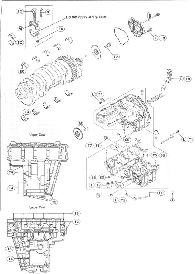
Exploded View

| T1: 12 N-m (1.2 kg-m, 104 in-lb) T2: 25 N-m (2.5 kg-m, 18.0 ft-lb) T3: 44 N-m (4.5 kg-m, 33 ft-lb) T4: 27 N-m (2.8 kg-m, 20 ft-lb) T5: 20 N-m (2.0 kg-m, 14.5 ft-lb) T6: See the text. T7: 15 N-m (1.5 kg-m, 11.0 ft-lb) T8: 4.9 N-m (0.50 kg-m, 43 in-lb) T9: 9.8 N-m (1.0 kg-m, 87 in-lb) T10: 125 N-m (13 kg-m, 94 ft-lb) |

1. Upper Alternator Chain Tensioner
2. Lower Alternator Chain Tensioner EO: Apply engine oil.
L: Apply a non-permanent locking agent. M: Apply molybdenum disulfide grease. R: Replacement Parts SS: Apply silicone sealant. G: Apply grease.
Specifications
| Item |
| Standard |
Service Limit
Alternator Chain:
Alternator chain 20 link length Crankshaft, Connecting Rods:
Connecting rod big end side clearance
Connecting rod big end bearing insert/crankpin clearance
Crankpin diameter:
Marking None
о
Connecting rod big end bore diameter: Marking None
о
Connecting rod big end bearing insert thickness:
Brown Colorless Blue
158.8 - 159.2 mm
0.13 - 0.38 mm 0.036 - 0.066 mm 34.984 - 35.000 mm 34 984 - 34.992 mm 34.993 - 35.000 mm 38.000 - 38.016 mm 38.000 - 38.008 mm 38.009 - 38.016 mm
| 159.8 mm 0.6 mm 0.10 mm 34.96 mm |
1.475 - 1.480 mm 1.480 ~ 1.485 mm 1.485 - 1.490 mm
Connecting rod big end bearing insert selection:
|
Connecting Rod Bolt Stretch (Usable Range) New connecting rod Used connecting rod Crankshaft side clearance Crankshaft runout Crankshaft main bearing insert/
journal clearance Crankshaft main journal diameter: Marking None
Crankcase main bearing bore diameter: Marking о
None
Crankshaft main bearing insert thickness:
Brown Colorless Blue
0.20 - 0.32 mm 0.24 - 0.36 mm 0.05 - 0.20 mm TIR 0.02 mm or less
0.020 - 0.044 mm 32.984 - 33.000 mm 32.984 ~ 32.992 mm 32.993 - 33.000 mm 36.000 - 36.016 mm 36.000 - 36.008 mm 36.009 - 36.016 mm
| 0.40 mm TIR 0.05 mm 0.07 mm 32.96 mm |
1.490 - 1.494 mm 1.494 - 1.498 mm 1.498 - 1.502 mm
Crankshaft main bearing insert selection:
|
| 'The bearing inserts for Nos. 2 and 4 journals have an oil groove, respectively. |
| Item | Standard | Service Limit |
| Transmission: | ||
| Shift fork ear thickness | 5.9 - 6.0 mm | 5.8 mm |
| Gear shift fork groove width | 6.05 - 6.15 mm | 6.25 mm |
| Shift fork guide pin diameter | 7.9 - 8.0 mm | 8.1 mm |
| Shift drum groove width | 8.05 - 8.20 mm | 8.3 mm |
Special Tools - Outside Circlip Pliers: 57001-144 Bearing Driver Set 57001-1129 Inside Circlip Pliers: 57001-143
Sealant - Kawasaki Bond (Silicone Sealant): 56019-120
Crankcase Splitting
Crankcase Splitting
• Remove the engine (see Engine Removal/Installation chapter). •Set the engine on a clean surface and hold the engine steady while
parts are being removed.
• Remove:
Clutch (see Clutch chapter) Alternator Chain (see Alternator Chain Removal) Oil Pump (see Engine Lubrication System chapter) Pickup Coil (see Electrical System chapter) *lf the crankshaft is to be removed, remove the pistons (see Engine Top End chapter).
*lf the alternator shaft is to be removed, remove the following. Alternator
Alternator Coupling (see Alternator Shaft, Starter Clutch Removal)
• Remove the upper crankcase bolts. О First loosen the 6 mm bolts.

|
6 mm Bolts [A] 8 mm Bolts [B]
• Remove the lower crankcase bolts. О First loosen the 6 mm bolts. 6 mm Bolts [A]
8 mm Bolt [B]
9 mm Bolts [C]

|
•Tap lightly around the crankcase mating surface with a plastic mallet, and split the crankcase. Take care not to damage the crankcase.
Crankcase Assembly