Главная страница Случайная страница
КАТЕГОРИИ:
АвтомобилиАстрономияБиологияГеографияДом и садДругие языкиДругоеИнформатикаИсторияКультураЛитератураЛогикаМатематикаМедицинаМеталлургияМеханикаОбразованиеОхрана трудаПедагогикаПолитикаПравоПсихологияРелигияРиторикаСоциологияСпортСтроительствоТехнологияТуризмФизикаФилософияФинансыХимияЧерчениеЭкологияЭкономикаЭлектроника
Final Drive
|
|
Table of Contents
Exploded View...................................................................................................................................... 10-2
Specifications....................................................................................................................................... 10-3
Drive Chain........................................................................................................................................... 10-4
Slack Inspection.............................................................................................................................. 10-4
Slack Adjustment............................................................................................................................ 10-4
Wheel Alignment Inspection Adjustment........................................................................................ 10-4
Drive Chain Wear Inspection.......................................................................................................... 10-5
Lubrication....................................................................................................................................... 10-5
Drive Chain Removal...................................................................................................................... 10-6
Drive Chain Installation.................................................................................................................. 10-6
Sprocket Coupling................................................................................................................................ 10-7
Engine Sprocket Removal.............................................................................................................. 10-7
Engine Sprocket Installation........................................................................................................... 10-7
Rear Sprocket Removal.................................................................................................................. 10-8
Rear Sprocket Installation.............................................................................................................. 10-8
Sprocket Wear Inspection............................................................................................................... 10-8
Rear Sprocket Warp Inspection...................................................................................................... 10-8
Coupling Bearing Removal............................................................................................................. 10-8
Coupling Bearing Installation.......................................................................................................... 10-9
Coupling Installation....................................................................................................................... 10-9
Coupling Bearing Inspection and Lubrication................................................................................ 10-9
Exploded View

|

|
G: Apply grease.
HO: Apply heavy oil.
I: Apply a non-permanent locking agent. 0: Apply oil. R: Replacement Parts
T1: 9.8 N-m (1.0 kg-m. 87 in-lb)
T2: 125 N-m (13.0 kg-m, 94 ft-lb)
T3: 74 N-m (7.5 kg-m, 54 ft-lb)
T4: 145 N-m (15.0 kg-m, 110 ft-lb)
_________________________________________________________________________ FINAL DRIVE 10-3
Specifications
| Item | Standard | Service Limit |
| Drive Chain: Standard chain Make Type Link Chain slack 20-link length | ENUMA EK50UV-X, Endless 112 links 10 ~ 15 mm 317.5 ~ 318.2 mm | Too tight: more than 15 mm Too loose: less than 10 mm 323 mm |
| Sprockets: Rear sprocket warp | 0.4 mm or less | 0.5 mm |
| Special Tools - Inside Clrclip Pliers: 57001-143 Bearing Driver Set 57001-1129 Jack: 57001-1238 |
Drive Chain
Slack Inspection
NOTE
О Check the slack with the motorcycle setting on its side stand. О Clean the chain if it is dirty, and lubricate it if it appears dry.
• Check the wheel alignment (see Wheel Alignment Inspection).
• Rotate the rear wheel to find the position where the chain is tightest
• Push up the chain at the rear end of the lower chain guard [A], and measure the distance (chain slack) [B] from the chain upper end to theswingarm [С].
*lf the chain slack exceeds the standard, adjust it
Chain Slack
Standard: 10 - 15 mm
Too Tight more than 15 mm

|
Too Loose: less than 10 mm
Slack Adjustment
• Loosen the both chain adjuster locknuts [А].
• Remove the cotter pin [B], and loosen the axle nut [С].
*lf the chain is too loose, turn out the left and right chain adjuster [D] evenly.
*lf the chain is too tight, turn in the left and right chain adjusters evenly, and kick the wheel forward.

|
•Turn both chain adjusters evenly until the drive chain has the correct amount of slack. To keep the chain and wheel properly aligned, the notch [E] on the left wheel alignment indicator [F] should align with the same swingarm mark or position [G] that the right indicator notch aligns with.
Л WARNING
Misalignment of the wheel will result in abnormal wear and may result in an unsafe riding condition.
•Tighten both chain adjuster locknuts securely.
•Tighten the axle nut Torque - Rear Axle Nut 145 N-m (15.0 kg-m, 110 ft-lb)
•Turn the wheel, measure the chain slack again at the tightest position, and readjust if necessary.
• Insert a new cotter pin and spread its ends.
Wheel Alignment Inspection Adjustment
•Check that the notch [A] on the left alignment indicator [B] aligns with the same swingarm mark or position [C] that the right alignment indicator notch aligns with.
*lf they are not, adjust the chain slack and align the wheel alignment (see Slack Adjustment).
NOTE

|
О Wheel alignment can be also be checked using the straightedge or string method.
AWARNING
Misalignment of the wheel will result In abnormal wear, and may result in an unsafe riding condition.
Drive Chain Wear Inspection
• Remove:
Chain Cover
• Rotate the rear wheel to inspect the drive chain for damaged rollers, and loose pins and links.
*lf there is any irregularity, replace the drive chain.
• Lubricate the drive chain if it appears dry.
• Stretch the chain taut by hanging a 98 N (10 kg, 20 lb) weight [A] on the chain.
• Measure the length of 20 links [B] on the straight part [C] of the chain from the pin center of the 1st pin to the pin center of the 21st pin. Since the chain may wear unevenly, take measurements at several places.
*lf any measurements exceed the service limit replace the chain. Also, replace the front and rear sprockets when the drive chain is replaced.
Drive Chain 20-1 Ink Length
Standard: 317.5 ~ 318.2 mm Service Limit 323 mm
AWARNING
If the drive chain wear exceeds the service limit replace the chain or an unsafe riding condition may result. A chain that breaks or jumps off the sprockets could snag on the engine sprocket or lock the rear wheel, severely damaging the motorcycle and causing it to go out of control.

|
For safely, use only the standard chain. It is an endless type and should not be cut for installation.
Lubrication
• If a special lubricant is not available, a heavy oil such as SAE 90 is preferred to a lighter oil because it will stay on the chain longer and provide better lubrication.

|
• If the chain appears especially dirty, clean it before lubrication.
_____________________ CAUTION ______________________
The O-rings between the side plates seal in the lubricant between the
pin and the bushing. To avoid damaging the O-rings and resultant
loss of lubricant, observe the following rules.
Use only kerosene or diesel oil for cleaning an O-rlng drive chain.
Any other cleaning solution such as gasoline or trichloroethylene will
cause deterioration and swelling of the O-ring.
Immediately blow the chain dry with compressed air after cleaning.

Complete cleaning and drying the chain within 10 minutes.
•Apply oil to the sides of the rollers so that oil will penetrate to the rollers and bushings. Apply the oil to the O-rings so that the O-rings will be coated with oil. •Wipe off any excess oil.
Drive Chain Removal • Remove:
Engine Sprocket (see Engine Sprocket Removal) Rear Wheel (see Wheels/Tires chapter) Chain Cover Screws [A] Chain Cover [B]
Swingarm (see Suspension chapter)
• Remove the drive chain [A] from the engine output shaft [В].
Drive Chain Installation • Install:
Swingarm (see Suspension chapter) Rear Wheel (see Wheels/Tires chapter) Engine Sprocket (see Engine Sprocket Removal) •Adjust the chain slack after installing the chain (see Slack Adjustment).
Sprocket, Coupling
Engine Sprocket Removal • Remove:
Lower Fairings (see Frame Chapter) Clutch Slave Cylinder (see Clutch chapter) Engine Sprocket Cover Bolts [A] Engine Sprocket Cover [B] Chain Cover
• Flatten out the bended washer [А].
• Remove the engine sprocket nut [B] and washer.
NOTE
О When loosening the engine sprocket nut hold the rear brake on.
• Using the jack, raise the rear wheel off the ground.
Special Tool - Jack: 57001-1238
• Loosen the drive chain (see Slack Adjustment).
• Remove the drive chain from the rear sprocket toward the right.
• Pull the engine sprocket [A] off the output shaft [B] along with the chain.
• Remove the engine sprocket.
Engine Sprocket Installation
• Replace the sprocket washer and axle cotter pin.
• Install the engine sprocket onto the output shaft with the drive chain engaged.
О Either side of the sprocket may be faced out.
•Apply oil to the threads of the output shaft and the seating surface of
the engine sprocket nut. •After torquing the engine sprocket nut[A], bend the one side[B] of the washer over the nut.
NOTE
О Tighten the nut while applying the rear brake.
Torque - Engine Sprocket Nut: 125 N-m (13.0 kg-m, 94 ft-lb)

|
•Adjust the drive chain slack after installing the sprocket (see Slack Adjustment).
Rear Sprocket Removal • Remove the rear wheel (see Wheel/Tires chapter).
______________________ CAUTION_____________________
Do not lay the wheel on the ground with the disc facing down. This can damage or warp the disc. Place blocks under the wheel so that the disc does not touch the ground.
• Remove the rear sprocket nuts [А].
• Remove the rear sprocket [В].
Rear Sprocket Installation
• Install the sprocket facing the tooth number marking [A] outward. •Tighten the rear sprocket nuts.
Torque - Rear Sprocket Nut: 74 N-m (7.5 kg-m, 54 ft-lb)
• Install the rear wheel (see Wheels/ Tires chapter).
Sprocket Wear Inspection
•Visually inspect the engine and rear sprocket teeth for wear and damage.
*lf the teeth are worn as illustrated, replace the sprocket, and inspect the drive chain wear (see Drive Chain Wear Inspection).
[A] Worn Tooth (Engine Sprocket)
[B] Worn Tooth (Rear Sprocket)
[C] Direction of Rotation
NOTE
О If a sprocket requires replacement the chain is probably worn also. When replacing a sprocket inspect the chain.
Rear Sprocket Warp Inspection
• Raise the rear wheel off the ground (see Wheels/Tires chapter) so that it will turn freely.
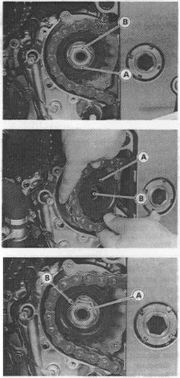
•Set a dial gauge [A] against the rear sprocket [B] near the teeth as shown, and rotate [C] the rear wheel to measure the sprocket runout (warp). The difference between the highest and lowest dial gauge readings is the amount of runout (warp). *lf the runout exceeds the service limit replace the rear sprocket.
Rear Sprocket Warp

Standard: 0.4 mm or less Service Limit 0.5 mm

|
• Remove the bearing by tapping from the wheel side. Special Tool - Bearing Driver Set: 57001-1129 [A]
Coupling Bearing Installation
• Replace the bearing with a new one.
• Press in the bearing until it is bottomed.
Special Tool - Bearing Driver Set: 57001-1129 [A]
• Pack the bearing with high temperature grease.
• Replace the circlip with a new one.

|
Special Tool - Inside Circlip Pliers: 57001-143
• Replace the grease seal with a new one.
• Press in the grease seal so that the seal surface is flush with the end of the hole.

|
OApply high temperature grease to the grease seal lips. Special Tool - Bearing Driver Set: 57001-1129 [A]
Coupling Installation •Grease the following and install the coupling. Ball Bearing [A] Coupling Grease Seal [B] Coupling Internal Surface [C]
Coupling Bearing Inspection and Lubrication
NOTE
О It is not necessary to remove the coupling bearing for inspection and lubrication. If the bearing is removed, it will need to be replaced with a new one.
•Wash the bearing with a high flash-point solvent, dry it (do not spin

it while it is dry), and oil it. Spin it by hand to check its condition. *lf it is noisy, does not spin smoothly, or has any rough spots, it must be replaced.
• Pack the bearing with good quality bearing grease. Turn the bearing around by hand a few times to make sure the grease is distributed uniformly inside the bearing.
Brakes
Table of Contents
Exploded View................................................................ 11-2
Specifications................................................................. 11-4
Brake Pedal.................................................................... 11-5
Brake Pedal Position Adjustment............................. 11-Б
Calipers.......................................................................... 11-6
Front Caliper Removal............................................. 11 -6
Rear Caliper Removal............................................. 11 -6
Caliper Installation................................................... 11 -6
Front Caliper Disassembly...................................... 11 -7
Front Caliper Assembly........................................... 11 -8
Rear Caliper Disassembly....................................... 11-8
Rear Caliper Assembly............................................ 11 -9
Brake Pads................................................................... 11-11
Front Brake Pad Removal....................................... 11-11
Front Brake Pad Installation................................... 11-11
Rear Brake Pad Removal....................................... 11-11
Rear Brake Pad Installation.................................... 11-11
Lining Wear............................................................. 11-12
Master Cylinder............................................................ 11-13
Front Master Cylinder Removal............................. 11-13
Front Master Cylinder Installation......................... 11 -13
Rear Master Cylinder Removal.............................. 11-13
Rear Master Cylinder Installation........................... 11-14
Front Master Cylinder Disassembly...................... 11-14
Rear Master Cylinder Disassembly....................... 11-14
Master Cylinder Assembly..................................... 11-15
Master Cylinder Inspection
(Visual Inspection).............................................. 11-15
Brake Disc.................................................................... 11-16
Brake Disc Removal............................................... 11-16
Brake Disc Installation............................................ 11-16
Brake Disc Wear..................................................... 11-16
Brake Disc Warp..................................................... 11-16
Brake Fluid................................................................... 11-17
Level Inspection...................................................... 11r17
Brake Fluid Change................................................ 11-17
Bleeding the Brake Line.......................................... 11-18
Brake Hose................................................................... 11-21
Brake Hose Removal/Installation......................... 11 -21
Brake Hose Inspection.......................................... 11 -21

Exploded View
U.S. Model Canadian Model Apply brake fluid. Apply grease.
Apply a non-permanent locking agent. Replacement Parts
| ZX900-B3 (other than US.CN Models) |
Follow the specific tightening sequence. Apply silicone grease (ex. PBC grease).
T1: 7.8 N-m (0.80 kg-m, 69 in-lb) T2: 25 N-m (2.5 kg-m, 18.0 ft-lb) T3: 1.0 N-m (0.10 kg-m, 9 in-lb) T4: 5.9 N-m (0.60 kg-m, 52 in-lb) T5: 1.5 N-m (0.15 kg-m, 13 in-lb) T6: 8.8 N-m (0.90 kg-m, 78 in-lb) T7: 6.9 N-m (0.70 kg-m, 61 in-lb) T8: 2.9 N-m (0.30 kg-m, 26 in-lb) T9: 34 N-m (3.5 kg-m, 25 ft-lb) T10: 21 N-m (2.1 kg-m, 15.0 ft-lb) T11: 23 N-m (2.3 kg-m, 16.5 ft-lb) T12: 18 N-m (1.8 kg-m, 13.0 ft-lb)

|
11-4 BRAKES Specifications
| Item | Standard | Service Limit |
| Brake Lever, Brake Pedal: Brake lever position Brake lever free play Pedal free play Pedal position | 4-way adjustable (to suit rider) Non-adjustable Non-adjustable About 43 mm below footpeg top | ------------------------------ |
| Brake Fluid: Grade Brand (recommended) | D.0.T.4 Castrol Girling-Universal Castrol GT (LMA) Castrol Disc Brake Fluid Check Shock Premium Heavy Duty | — — — |
| Brake Pads: Lining thickness: Front Rear | 4 mm 5 mm | 1 mm 1 mm |
| Brake Discs: Thickness: Front Rear Runout | 4.8 ~ 5.2 mm 5.8 ~ 6.1 mm 0.2 mm or less | 4.5 mm 5.5 mm 0.3 mm |
| Special Tools - Inside Circlip Pliers: 57001-143 Jack: 57001-1238 |
Brake Pedal
Brake Pedal Position Adjustment • Check that the brake pedal [A] is in the correct position. [B] Footpeg
Pedal Position [C]
Standard: About 43 mm below top of footpeg
*lf it is not, adjust the brake pedal position.
NOTE
О Usually it is not necessary to adjust the pedal position, but always adjust it when the master cylinder is disassembled.
•When the brake pedal is in its rest position, measure the length indicated in the figure.
Length [A]
Standard: 67 ± 1 mm
*lf the length is not within the specified length, adjust the hex head
[B] as following. О Loosen the bracket locknut [C]. OTum the hex head to obtain the specified length. О Tighten the locknut.
Torque - Rear Master Cylinder Bracket Locknut: 18 Nwn (1.8 kg-m, 13.0 ft-lb)
NOTE
Off the pedal position cannot be adjusted by turning the hex head, the brake pedal may be deformed or incorrectly installed.

•Check the brake light switch operation (see Rear Brake Light Switch Adjustment in Electrical System chapter).
Calipers
Front Caliper Removal
•Loosen the banjo bolt [A] at the brake hose lower end, and tighten it loosely.
• Unscrew the caliper mounting bolts [B], and detach the caliper [C] from the disc.