Главная страница Случайная страница
КАТЕГОРИИ:
АвтомобилиАстрономияБиологияГеографияДом и садДругие языкиДругоеИнформатикаИсторияКультураЛитератураЛогикаМатематикаМедицинаМеталлургияМеханикаОбразованиеОхрана трудаПедагогикаПолитикаПравоПсихологияРелигияРиторикаСоциологияСпортСтроительствоТехнологияТуризмФизикаФилософияФинансыХимияЧерчениеЭкологияЭкономикаЭлектроника
CAUTION___
|
|

|
Immediately wash away any brake fluid that spills.
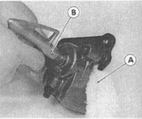
Rear Caliper Removal
• Loosen the banjo bolt [A] at the brake hose lower end, and tighten it loosely.
• Unscrew the caliper mounting bolts [B], and detach the caliper [C] from the disc.
• Unscrew the banjo bolt and remove the brake hose [D] from the caliper (see Brake Hose Removal/Installation).
______________________ CAUTION_______
Immediately wash away any brake fluid that spills.
NOTE
О If the caliper is to be disassembled after removal and if compressed air is not available, disassemble the caliper before the brake hose is removed (see Rear Caliper Disassembly).
Caliper Installation
• Install the caliper and brake hose lower end.
О Replace the washers that are on each side of hose fitting with new ones.
•Tighten the caliper mounting bolts and banjo bolt.
Torque - Caliper Mounting Bolts (Front): 34 N-m (3.5 kg-m, 25 ft-lb) Caliper Mounting Bolts (Rear): 25 N-m (2.5 kg-m. 18.0 ft-lb) Brake Hose Ban|o Bolt: 25 N-m (2.5 kg-m, 18.0 ft-lb)
•Check the fluid level in the brake reservoirs.
• Bleed the brake line (see Bleeding the Brake Line).

|
•Check the brake for good braking power, not brake drag, and no fluid leakage.
AWARNING
Do not attempt lo drive the motorcycle until a hill brake lever or pedal is obtained by pumping the brake lever or pedal until the pads are against the disc. The brakes will no! function on the lirst application of the lever or pedal if this is not done.
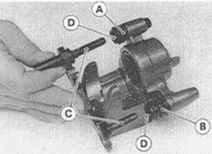
Front Caliper Disassembly
• Remove the pad spring and brake pads (see Front Brake Pad Removal).
• Remove the front caliper.
• Remove the front caliper assembly bolts [A] and split the front caliper.

|
• Remove the piston insulators and the O-rings.
• Using compressed air, remove the pistons. One way to remove the pistons is as follows.
О Install a rubber gasket [A] and a wooden board [B] more than 10 mm thick on the caliper half, and fasten them together with a suitable bolt and nut as shown. Leave one of the oil passages [C] open.
О Lightly apply compressed air [D] to the oil passage until the pistons hit the rubber gasket. Block the hose joint opening [E] during this operation if the caliper half has the opening.
[F] Bolt and Nut
[G] Oil Passage sealed by Rubber Gasket.

|
[H] Push down.
AWARNING
To avoid serious injury, never place your fingers or palm In front of the piston. If you apply compressed air into the caliper, the piston may crush your hand or fingers.
О Pull out the pistons by hand.
• Remove the dust seals [A] and fluid seals [В].
• Remove the bleed valve [C] and rubber cap [D].

|
• Repeat the previous step to remove the pistons from the other side of the caliper body.
Front Caliper Assembly

|
•Clean the caliper parts except for the pads.
| CAUTION | |
| For cleaning the parts, ш | le only disc brake fluid, isopropyl alcohol, |
| or ethyl alcohol. |
• Install the bleed valve and rubber cap. Torque - Bleed Valve: 7.8 N-m (0.80 kg-m, 69 in-t>)
• Replace the fluid seals [A] with new ones.
О Apply brake fluid to the fluid seals, and install them into the cylinders by hand.
• Replace the dust seals [B] with new ones if they are damaged.

|
О Apply brake fluid to the dust seals, and install them into the cylinders by hand.
• Replace the O-rings [A] if they are damaged.
•Apply brake fluid to the outside of the pistons, and push them into each cylinder by hand.
• Be sure to install the O-rings. •Tighten the caliper assembly bolts.
Torque - Front Caliper Assembly Bolts: 21 N-m (2.1 kg-m, 15.0 ft-lb)
|
• Install the piston insulators [В].
• Install the pads (see Front Brake Pad Installation). •Wipe up any spilled brake fluid on the caliper with wet cloth.
Rear Caliper Disassembly
• Remove the rear caliper.
• Remove the pads and anti-rattle spring (see Rear Brake Pad Removal).
• Remove the piston insulator.
• Using compressed air, remove the piston.
О Cover the caliper opening with a clean, heavy cloth [А]. О Remove the piston by lightly applying compressed air [B] to where the brake line fits into the caliper.
AWARNING
To avoid serious injury, never place your fingers or palm inside the caliper opening. If you apply compressed air inlo the caliper, the piston may crush your hand or fingers.
• Remove the dust seal and fluid seal.
• Remove the bleed valve and rubber cap.
NOTE
О If compressed air is not available, do as follows with the brake hose
connected to the caliper. О Prepare container for brake fluid, and perform the work above it О Remove the pads and spring (see Rear Brake Pad Removal). О Pump the brake pedal to remove the caliper piston.
Rear Caliper Assembly
•Clean the caliper parts except for the pads.
_____________________ CAUTION __________

|
For cleaning the parts, use only disc brake fluid, isopropyl alcohol, or elhyl alcohol.
• Install the bleed valve and rubber cap. Torque - Bleed Valve: 7.8 N-m (0.80 kg-m, 69 in-lb)
• Replace the fluid seal [A] with a new one.
О Apply brake fluid to the fluid seal, and install it into the cylinder by hand.
• Replace the dust seal [B] with a new one if it is damaged.
|
OApply brake fluid to the dust seal, and install it into the cylinder by hand.
•Apply brake fluid to the outside of the piston, and push it into the cylinder by hand.
• Replace the shaft rubber friction boot [A] and dust cover [B] if they are damaged.
•Apply a thin coat of PBC (Poly Butyl Cuprysil) grease to the caliper holder shafts [C] and holder holes [D] (PBC is a special high temperature, water-resistance grease).
• Install the anti-rattle spring [A] in the caliper as shown. ^^^^^^^^^
• Install the piston insulator.
• Install the pads (see Rear Brake Pad Installation). (л) •Wipe up any spilled brake fluid on the caliper with wet cloth.
Brake Pads
Front Brake Pad Removal
• Unscrew the caliper mounting bolts.
• Detach the caliper from the disc.
• Unscrew the pad spring screws [A], and remove the pad spring [В].
• Draw out the clip [A], and take off the pad pin [В].
• Remove the brake pads [С].
Front Brake Pad Installation
• Push the caliper pistons in by hand as far as they will go.
• Install the brake pads.
• Install the pad pin and clip. The clip must be " outside" of the pads.

|
• Install the caliper (see Caliper Installation).
44 WARNING
Do not attempt to drive the motorcycle until a full brake lever Is obtained by pumping the brake lever until the pads are against the disc. The brake will not function on the first application of the lever if this is not done.
Rear Brake Pad Removal
• Unscrew the caliper mounting bolts.
• Detach the caliper from the disc.
• Draw out the clip [A], and take off the pad pin [В].
• Remove the brake pads [С].
Rear Brake Pad Installation
• Push the caliper piston in by hand as far as it will go.
• Install the anti-rattle spring in place.
• Install the brake pads.
• Install the pad pin and clip. The clip must be " outside" of the pads.

• Install the caliper (see Caliper Installation).
AWARNING
Do not attempt to drive the motorcycle until a full brake pedal is obtained by pumping the brake pedal until the pads are against the disc. The brake will not function on the first application of the pedal If Viis is not done.
Lining Wear
• Check the lining thickness of the pads in each caliper. *lf the lining thickness of either pad is less than the service limit [A], replace both pads in the caliper as a set
Pad Lining Thickness
Standard: Front [B] 4 mm
Rear [C] 5 mm

|
Service Limit 1 mm
Master Cylinder
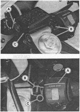
Front Master Cylinder Removal • Disconnect the front brake light switch connectors [А].
• Remove the banjo bolt [A] to disconnect the brake hose from the master cylinder (see Brake Hose Removal/Installation).
• Unscrew the clamp bolts [B], and take off the master cylinder [C] as an assembly with the reservoir, brake lever, and brake switch installed.
Front Master Cylinder Installation
• Install the front master cylinder so that the mating surface [A] of the switch housing is aligned with the mating surface [B] of the master cylinder clamp to level the reservoir. •The master cylinder clamp must be installed with the arrow mark [C] upward.
•Tighten the upper clamp bolt first, and then the lower clamp bolt. There will be a gap at the lower part of the clamp after tightening.
Torque - Front Master Cylinder Clamp Bolts: 8.8 N-m (0.90 kg-m, 78 Mb)
• Replace the washers that are on each side of the hose fitting with new ones.
•Tighten the brake hose banjo bolt Torque - Brake Hose Ban|o Bolt 25 N-m (2.5 kg-m, 18.0 ft-lb)
• Bleed the brake line (see Bleeding the Brake Line).

|
• Check the brake for good braking power, no brake drag, and no fluid leakage.
Rear Master Cylinder Removal
• Pull off the reservoir hose lower end [A], and drain the brake fluid into a container.
• Unscrew the brake hose banjo bolt [B] on the master cylinder (see Brake Hose Removal/Installation).
• Remove the cotter pin.
• Pull off the joint pin [С].
NOTE
О Pull off the joint pin while pressing down the brake pedal.

|
|
• Unscrew the master cylinder mounting bolts [D], and take off the master cylinder [E] and master cylinder cover [F].
. v Master Cylinder Installation
• Replace the cotter pin with a new one.
• Replace the washers that are on each side of hose fitting with new ones.
•Tighten the following bolts.
Torque - Rear Master Cylinder Mounting Bolls: 23 N-m (Z3 kg-m, 16.5 fl-lb)
Brake Hose Banjo Bolt 25 N-m (2 J kg-m, 18.0 ft-lb)
• Bleed the brake line (see Bleeding the Brake Line).
• Check the brake for good braking power, no brake drag, and no fluid leakage.
Front Master Cylinder Disassembly
• Remove the front master cylinder.
• Remove the reservoir cap and diaphragm, and pour the brake fluid into a container.
• Unscrew the locknut and pivot bolt and remove the brake lever.
• Push the dust cover out of place, and remove the circlip.
Special Tool - Inside Circlip Pliers: 57001-143
• Pull out the piston [A], secondary cup [B], primary cup [C], and return spring [D].
______________ CAUTION_____________________

|
Do not remove the secondary cup from toe piston since removal will damage It
Rear Master Cylinder Disassembly
• Remove the rear master cylinder.
•Slide the dust cover on the push rod out of place, and remove the circlip.
Special Tool - Inside Circlip Pliers: 57001-143
• Pull out the push rod with the piston stop.
•Take off the piston [A], secondary cup [B], primary cup [C], and return spring [D].
______________________ CAUTION____________________

|
Do not remove the secondary cup from the piston since removal will damage It
Master Cylinder Assembly
• Before assembly, clean all parts including the master cylinder with brake fluid or alcohol.
CAUTION
Except for the disc pads and disc, use only disc brake fluid, isopropyl alcohol, or ethyl alcohol for cleaning brake parts. Do not use any other fluid for cleaning these parts, Gasoline, engine oil, or any other petroleum distillate will cause deterioration of the rubber parts. Oil spilled on any part will be difficult to wash off completely, and will eventually deteriorate the rubber used in the disc brake.
•Apply brake fluid to the removed parts and to the inner wall of the cylinder.
•Take care not to scratch the piston or the inner wall of the cylinder. •Tighten the brake lever pivot bolt and the locknut.
Torque - Brake Lever Pivot Bolt 1.0 N-m (0.10 kg-m, 9 In-lb)

|
Brake Lever Pivot Bolt Locknut 5.9 N-m (0.60 kg-m, 52 IrHb)
Master Cylinder Inspection (Visual Inspection)
• Disassemble the front and rear master cylinders.
•Check that there are no scratches, rust or pitting on the inner wall of each master cylinder [A] and on the outside of each piston [В].
*lf a master cylinder or piston shows any damage, replace them.
• Inspect the primary [C] and secondary [D] cups.
*lf a cup is worn, damaged softened (rotted), or swollen, the piston assembly should be replaced to renew the cups.

|
*lf fluid leakage is noted at the brake lever, the piston assembly should be replaced to renew the cups.
•Check the dust covers [E] for damage.
*lf they are damaged, replace them.
•Check that relief [F] and supply [G] ports are not plugged.
*lf the relief port becomes plugged, the brake pads will drag on the disc.
Blow the ports clean with compressed air. •Check the piston return springs [H] for any damaged. *lf the springs are damaged, replace them.
Brake Disc
Brake Disc Removal
• Remove the wheel (see Wheels/Tires chapter).

|
• Unscrew the mounting bolts, and take off the disc.
Brake Disc Installation
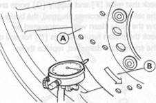
• Install the brake disc [A] on the wheel so that its rotation mark [B] aligns with the tire rotation [C] indicated by the arrow on the tire sidewall.

|
•Tighten the mounting bolts [D]. Torque - Brake Disc Mounting botts: 23 N-m (2.3 kg-m, 16.5 ft-lb)
Brake Disc Wear
♦ Replace the disc [A] if it has worn past the service limit. [B] Measuring Area
Front Disc Thickness
Standard: 4.8 ~ 5.2 mm Service Limit 4.5 mm
Rear Disc Thickness
|
Standard: 5.8 ~ 6.1 mm Service Limit 5 J mm
Brake Disc Warp
•Jack up the motorcycle so that the wheel is off the ground.
Special Tool - Jack: 57001-1238
• For front disc inspection, turn the handlebar fully to one side. •Set up a dial gauge against the disc [A] as shown and measure disc runout
[B] Turn the wheel by hand. *lf runout exceeds the service limit, replace the disc.
Disc Runout
Standard: 0.2 mm or less Service Limit 0.3 mm
Brake Fluid
Level Inspection
• Check that the brake fluid level in the front brake reservoir [A] is above the lower level line [В].

NOTE
О Hold the reservoir horizontal by turning the handlebar when checking brake fluid level.
*lf the fluid level is lower than the lower level line, fill the reservoir to the upper level line [A] in the reservoir [В].
• Remove the seat, and check that the brake fluid level in the rear brake
reservoir [A] is between the upper [B] and the lower [C] level lines. *lf the fluid level is lower than the lower level line, fill the reservoir to the upper level line.
AWARNING
Change the brake fluid in the brake line completely if the brake fluid must be refilled but the type and brand of the brake fluid «Ml Is already in the reservoir are unidentified. After changing the fluid, use only the same type and brand of fluid thereafter.
Recommended Disc Brake Fluid Grade: D.O.T.4
Brand: Castrol Glrling-Universal Castrol GT (LM A) Castrol Disc Brake Fluid Check Shock Premium Heavy Duty
Brake Fluid Change
NOTE
О The procedure to change the front brake fluid is as follows. Changing the rear brake fluid is the same as for the front brake.
• Level the brake fluid reservoir.
• Remove the reservoir cap.
• Remove the rubber cap from the bleed valve [A] on the caliper. •Attach a clear plastic hose [B] to the bleed vatve, and run the other
end of the hose into a container.
• Fill the reservoir with fresh specified brake fluid.
• Change the brake fluid as follows:
О Repeat this operation until fresh brake fluid comes out from the plastic hose or the color of the fluid changes.
1. Open the bleed valve [А].
2. Apply the brake and hold it [В].
3. Close the bleed valve [С].
4. Release the brake [D].
NOTE
О The fluid level must be checked often during the changing operation and replenished with fresh brake fluid. If the fluid in the reservoir runs out any time during the changing operation, the brakes will need to be bled since air will have entered the brake line. О Front Brake: Repeat the above steps for the other caliper. О Rear Brake: Repeat the above steps for the other bleed valve.
• Remove the clear plastic hose.
• Install the reservoir cap.
•Tighten the bleed valve, and install the rubber cap.
Torque - Bleed Valve: 7Л N-m (0.80 kg-m, 69 In-lb)

•After changing the fluid, check the brake for good braking power, no
brake drag, and no fluid leakage. *lf necessary, bleed the air from the lines.
Bleeding the Brake Line
The brake fluid has a very low compression coefficient so that almost all the movement of the brake lever or pedal is transmitted directly to the caliper for braking action. Air, however, is easily compressed. When air enters the brake lines, brake lever or pedal movement will be partially used in compressing the air. This will make the lever or pedal feel spongy, and there will be a loss in braking power.
AWARNING
Be sure to bleed the air from the brake fine whenever brake fever or pedal action feels soft or spongy after the brake fluid is changed, or whenever a brake line fitting has been loosened for any reason.
NOTE
О The procedure to bleed the front brake line is as follows. Bleeding the rear brake line is the same as for the front brake.
• Remove the reservoir cap, and fill the reservoir with fresh brake fluid to the upper level line in the reservoir.
•With the reservoir cap off, slowly pump the brake lever several times until no air bubbles can be seen rising up through the fluid from the holes at the bottom of the reservoir. О Bleed the air completely from the master cylinder by this operation.
• Install the reservoir cap.
• Remove the rubber cap from the bleed valve on the caliper. •Attach a clear plastic hose to the bleed valve, and run the other end of
the hose into a container.
• Bleed the brake line and the caliper as follows:
О Repeat this operation until no more air can be seen coming out into the plastic hose.
1. Pump the brake lever until it becomes hard, and apply the brake and hold it [А].
2. Quickly open and close[B] the bleed valve while holding the brake applied.
3. Release the brake [С].
NOTE
О The fluid level must be checked often during the bleeding operation and replenished with fresh brake fluid as necessary. If the fluid in the reservoir runs completely out any time during bleeding, the bleeding operation must be done over again from the beginning since air will have entered the line. О Tap the brake hose lightly from the caliper to the reservoir for more
complete bleeding. О Front Brake: Repeat the above steps for the other caliper. О Rear Brake: Repeat the above steps for the other bleed valve.
• Remove the clear plastic hose.
•Tighten the bleed valve, and install the rubber cap.
Torque - Bleed Valve: 7.8 N-m (0.80 kg-m, 69 kvlb)
• Check the fluid level.

|
•After bleeding is done, check the brake for good braking power, no brake drag, and no fluid leakage.
A WARNING
When working with the disc brake, observe the precautions listed
below.
1. Never reuse old brake fluid.
2. Do not use fluid from a container that has been left unsealed or that has been open for a long time.
3. Do not mix two types and brands of fluid for use in the brake. This lowers the brake fluid boiling point and could cause the brake to be ineffective. It may also cause the rubber brake parts to deteriorate.
4. Don't leave the reservoir cap off for any length of time to avoid moisture contamination of the fluid.
5. Don't change the fluid in the rain or when a strong wind is blowing.
6. Except for the disc pads and disc, use only disc brake fluid, isopropyl alcohol, or ethyl alcohol for cleaning brake parts. Do not use any other fluid for cleaning these parts. Gasoline, engine oil, or any other petroleum distillate will cause deterioration of the rubber parts. Oil spilled on any part will be difficult to wash off completely and will eventually deteriorate the rubber used in the disc brake.
7. When handling the disc pads or disc, be careful that no disc brake fluid or any oil gets on them. Clean off any fluid or oil that inadvertently gets on the pads or disc with a high-flash point solvent. Do not use one which will leave an oily residue. Replace the pads with new ones if they cannot be cleaned satisfactorily.
8. Brake fluid quickly ruins painted surfaces; any spilled fluid should be completely wiped up immediately.
9. If any of the brake line fittings or the bleed valve is opened at any time, the AIR MUST BE BLED FROM THE BRAKE UNE.
Brake Hose
Brake Hose Removal'/Installation
______________________ CAUTION_____________________
Brake fluid quickly ruins painted or plastic surfaces; any spilled fluid should be completely wiped up immediately with wet cloth.
•When removing the brake hose, take care not to spill the brake fluid
on the painted or plastic parts. •When removing the brake hose, temporarily secure the end of the brake
hose to some high place to keep fluid loss to a minimum. •There are washers on each side of the brake hose fitting. Replace them
with new ones when installing. •When installing the hoses, avoid sharp bending, kinking, flattening or twisting, and route the hoses according to Hose Routing section in General Information chapter. •Tighten the banjo bolts at the hose fittings.
Torque - Brake Hose Ban|o Bolts: 25 N-m (2.5 kg-m, 18.0 ft-lb)
• Bleed the brake line after installing the brake hose (see Bleeding the Brake Line).
Brake Hose Inspection
•The high pressure inside the brake line can cause fluid to leak or the hose to burst if the line is not properly maintained. Bend and twist the rubber hose while examining it. * Replace it if any cracks or bulges are noticed.