Главная страница Случайная страница
КАТЕГОРИИ:
АвтомобилиАстрономияБиологияГеографияДом и садДругие языкиДругоеИнформатикаИсторияКультураЛитератураЛогикаМатематикаМедицинаМеталлургияМеханикаОбразованиеОхрана трудаПедагогикаПолитикаПравоПсихологияРелигияРиторикаСоциологияСпортСтроительствоТехнологияТуризмФизикаФилософияФинансыХимияЧерчениеЭкологияЭкономикаЭлектроника
Example 3
|
|
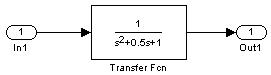
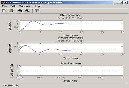
Fig.4.9 The transfer function of the control system in question and its characteristics (step response, impulse response and pole-zero map).
- Harmonic input signal.
Example 4
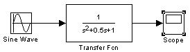
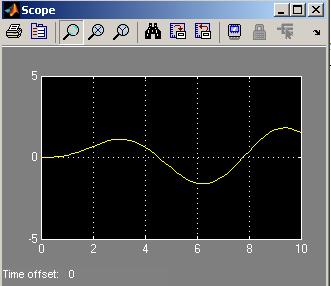
Fig.4.10 The transfer function of the control system in question and its response to the sine wave input signal
This input signal may be represented in the following forms:
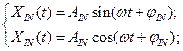 (4.42)
where:
 - a circular frequency of oscillation
 - a period of oscillation
 - a phase shift.
Harmonic input signal may be represented in the complex form:
 (4.43)
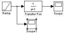
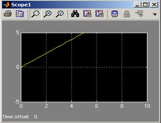
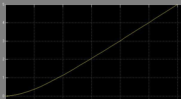
D. Linear increasing (ramp) signal.
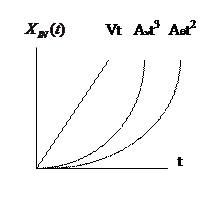
Fig.4.11 Linear increasing (ramp) signal, quadratic and cubic power time functions
A ramp function may be defined according to Eq. (4.44):
 (4.44)
where  - a constant coefficient.
This function may be referred as a “constant velocity input”.
Example 5